For this week's question, you need to have a bit of background on vectors. You may not have studied vectors before. In that case, look up vectors for a brief introductory lesson that will provide the necessary background including an explanation of the notation. You should also review the July 19 question.
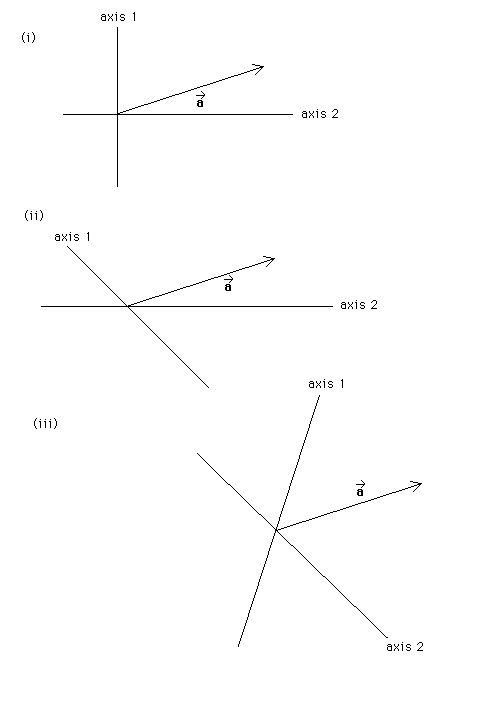
Parts (i), (ii), and (iii) of the following diagram each show the same vector a* and two axes, labelled 1 and 2. The two axes are different in each case. In each case, construct two vectors, a1* and a2*, such that a1* is oriented along axis 1 and a2* along axis 2 and such that a1* + a2* = a*.

Answer. The vectors that lie along the two axes and whose sum is equal to the given vector are called 'component vectors'. As the following construction will make clear, a given vector has two uniquely determined component vectors. The number 'two' applies if we are dealing with vectors in a two-dimensional space, as in the present case. In a three-dimensionals space, any given vector will have three uniquely determined component vectors, once three axes are specified. The component vectors of a given vector depend on how the axes are chosen.
The method that allows us to find the component vectors is the method of 'parallel projection onto the axes'. This method will now be explained for part (i).
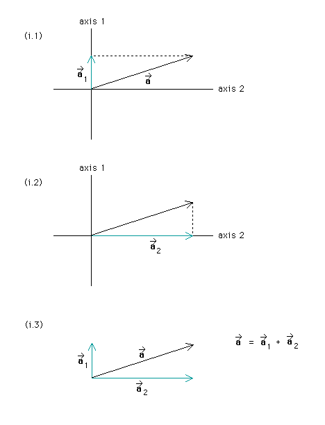
The next figure, with diagrams (i.1), (i.2), and (i.3), explains how to find the component vectors in case (i). To find the component vector for axis 1, one has to parallel-project vector a* onto axis 1. To do this pretend you are shining a beam of parallel light rays that are all parallel to axis 2 onto vector a*. (The ray through the tip of vector a* is indicated by a stippled line). Then vector a* will throw a shadow onto axis 1. This shadow is the component vector along axis 1. We will denote it a*1. See the following diagram (i.1). What this projection parallel to axis 2 accomplishes is to subtract the component vector along axis 2. We are left with the component vector along axis 1.

Diagram (i.2) above shows the analogous parallel projection along axis 1. It subtracts the component along axis 1 and leaves us with the component vector along axis 2, denoted a*2. Diagram (i.3) above shows vector a* and its two component vectors a*1 and a*2. You can see that the sum of the two component vectors is equal to a*. Given these two axes, there are no other two vectors that lie along these axes and whose sum is equal to a*. Try to find some, if you like.
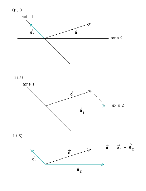
As case (ii) shows, the component vectors for a given vector a* are different if different axes are chosen. Diagrams (ii.1), (ii.2), and (iii.3) show the same parallel-projection process, in step-by-step fashion, and the resulting component vectors for case (ii).

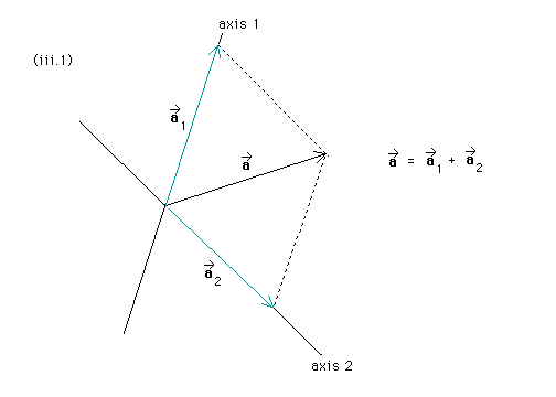
Diagram (iii.1) below shows the parallel projection and resultant component vectors for case (iii).
