|
|
|
|
Click on a number to view the explanation of the corresponding item.
There are four basic control buttons. They are, from left to right:
 Rewind. Resets the simulation to the initial
position with the previously chosen initial values. If
you have the particle path displayed, Rewind will allow
you to compare paths traversed under different
conditions, e.g., different initial velocities.
After clicking Rewind, click Play to restart the motion.
 Play/Pause. Starts the motion.
After Play has been clicked, the button will change
into the Pause button  .
.
Clicking Pause will freeze the motion. To resume the motion, click Play once more.
 Step. Lets you step through the motion in equal
time steps. The size of the time steps can be adjusted
by means of the Time Step slider. See Point 9 below.
 Reset. Resets the applet to its default
setting.
Adjustments in the initial conditions can only be made after first clicking REWIND or RESET.

Displays or hides the paths of the two balls. Ball 1 is the red ball, and its path is shown in red. Ball 2 is the yellow ball, and its path is shown in yellow.
The paths are not erased when you click the Rewind button.

Displays an x,y coordinate grid that makes it easier to judge the balls' positions. The x-axis points to the right and the y-axis points upward.

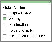
This toggle button displays or hides the Vector Panel shown below on which you can select the vectors that you want to have displayed. Only one vector, the velocity, is selected in the Vector Panel shown below. This corresponds to what is shown in the image at the top of this Help document.
Five vectors can be displayed: Position in cyan, Velocity in magenta, Acceleration in orange, Force of Gravity in green, and Force of Air Resistance in red. Only Ball 2 (yellow ball) can experience air resistance.


When the Components toggle button is selected, the x and y components of the velocity vectors of the two balls are displayed in pale magenta. To hide the components, click the button a second time.

When this button is selected, clicking anywhere in the
applet window will place a bull's eye target  at the point clicked.
The (x,y)-coordinates of the target's
location will be displayed as long as the mouse button is
depressed. Dragging with the mouse lets you drag the
target to another location. Clicking on the target will
remove the target, but only if the Target button is
selected.

When the Coordinates button is selected, clicking anywhere in the applet window will place a "+" marker at the point clicked and display the x,y coordinates of the point. This way you can measure the coordinates of a point. The point can be dragged to a new location as long as the mouse button is depressed. Clicking on a "+" will remove it, but only if the Coordinates button is selected at the time.


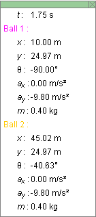
Displays or hides the draggable Data box shown above. The box contains the following information:
and for each ball separately:
The values shown in the sample image of a Data box above apply to the image at the top of this Help document.

There are four sliders. The first two, for adjusting the size of the time step, the magnitude g of the acceleration due to gravity, apply to the applet globally. The last two, the drag coefficient C, and the mass m, apply only to Ball 2 (yellow ball).
The time step can be varied from 0 to 1.00 s in steps of 0.01 s, g from 0 to 20.0 m/s2 in steps of 0.1 m/s2, C from 0 to 0.020 kg/m in steps of 0.001 kg/m, and m from 0.1 kg to 1.0 kg in steps of 0.1 kg.
Clicking on a slider to the left or right of the slider tab allows fine adjustment of the slider setting.
Clicking on the Input Dialog button  of a slider will open a dialog for entering an exact
value for the slider setting. The dialog for the
g-slider is illustrated below. The range in which
values can be entered, from 0.0 m/s2 to 20.0
m/s2 in this case, is indicated above the data
entry field.


Four data entry fields are provided for setting the x and y components of the initial velocities of the two balls.
After typing new values into one or two of the fields, press ENTER to make them effective.
During the motion, these entry fields are constantly being updated and show the current velocity.
When the velocity vectors are displayed, the velocity of either ball can also be changed by dragging the tip of its velocity vector.
The velocities can only be adjusted after REWIND or RESET, not when the motion is paused.
There are two balls, Ball 1 which is red and Ball 2 which is yellow. Before starting the motion, you can drag each ball to a desired starting position. The balls' x and y position coordinates are displayed in the Data box. They are updated throughout the motion, along with the values of other variable quantities.
If you hold the Shift key down while dragging a ball, the ball will move only vertically. This makes it easier to set the ball to a given initial position because one does not have to control the ball's horizontal and vertical coordinates at once. Displaying the Grid may also help in dragging a ball to a specific location.